MFSK 2000
Transmitting MFSK
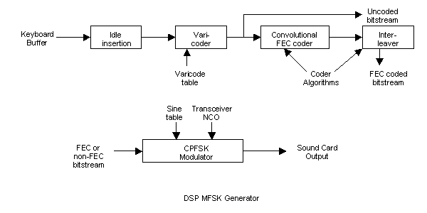
Transmitting MFSK is very simple. The data (say from the keyboard) is stored in a buffer, and once the transmitter is started, is sent on via a series of coders to the transmit modulator, then to the sound card for conversion to audio.
Study the top half of the diagram after this section.
The Varicoder used for MFSK 2000 is similar to, but not the same that used for PSK31. In particular, the need for continuous "00" signals to identify idle is not required, and so a more efficient code utilising combinations with repeated zeros is possible. Other codes outside the 256 character ASCII set are used for control purposes.
The following example was generated using a table and skipping algorithm exactly as described, but using a spreadsheet. The apparent sine wave represents four symbols weighted 010, 100, 000, 010, and is actually four frequencies - four sequential symbols - which might represent tones of 1008, 1012, 1000 and 1008 Hz. Each symbol has approximately 10 cycles, but because of the smooth transition from one to the next, you really can't tell. Using a ruler you might see the difference in frequency, but as is obvious, the phase is continuous.
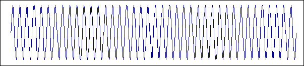
When the number of samples skipped is fixed, a constant frequency is generated. However when the number of samples skipped changes, a different frequency is generated, and the frequency of the sine wave generated smoothly changes from one frequency to the next, without the phase changing. This technique is called Continuous Phase Frequency Shift Keying, or CPFSK, and generates the cleanest possible FSK signal.
The technique of sampling a table in steps is called a Direct Digital Synthesizer. Many modern HF rigs use this technique for the "VFO". In the CPFSK modulator, the number of entries skipped is controlled by three, four, or five bits of data from the coders, depending on the number of tones selected. The speed at which tones are switched depends on the selected baud rate.
Look at the lower part of the above block diagram. All this functionality is in the one block entitled "CPFSK Modulator". Because the transmitter signal is generated "on frequency" to avoid mixing, the transceiver NCO used by the receiver cannot be used directly (since it runs at about 1/4 the transmit frequency). However, the software knows the receiver division ratio and the NCO offset, so adds these factors into the transmitter table skipping algorithm.
Thus the Transmitter and Receiver operate as a "Transceiver", on the same frequency. Finally, the stream of values are sent to the PC sound card for conversion to audio tones to be sent to the transmitter. There is no variation in amplitude in the MFSK signal - only the frequency changes. The signal consists only of sine waves and needs no further filtering.
Each of the tones in a particular mode are assigned a bit value, for example for 8 tones, the values are:
   8 Tones:                      16 Tones:
   Tone         Weight           Tone         Weight           Tone         Weight
    0 (lowest)   000              0 (lowest)   0000             8            1100
    1            001              1            0001             9            1101
    2            011              2            0011            10            1111
    3            010              3            0010            11            1110
    4            110              4            0110            12            1010
    5            111              5            0111            13            1011
    6            101              6            0101            14            1001
    7 (highest)  100              7            0100            15 (highest)  1000
So the transmitter has a small table which defines for each group of three four or five bits
to be transmitted, which tone to use. Notice that the "weight" of each tone does not
increase in binary order. This is to ensure that if there is a mis-tuning error, the
maximum bit error is one bit. If the order was binary, for example, the transition
from "011" to "100", which involves changing all three bits, could cause serious error.
This is called a "Gray" code.
8 Tones:                    16 Tones:                      32 Tones:
  ADGJMPSVY2...                AEIMQUY...                      AFKPUZ...
  BEHKNQTWZ3...                BFJNRVZ...                      BGLQV1...
  CFILORUX14...                CGKOSW0...                      CHMRW2...
                               DHLPTX1...                      DINSX3...
                                                               EJOTY4...
The bits are arranged as they arrive, but are sent on diagonally. The first
group of bits sent has been highlighted in each case in the above table. So the bits sent are:
 8 Tones: AEI DHL GKO JNR MQU PTX SW1 UZ4 ...
16 Tones: AFKP EJOT INSX MRW1 ...
32 Tones: AGMSY FLRX4 KQW39 ...
Once again the first group of bits sent on in each case is highlighted. The spreading of the bits is quite modest since the table is not very deep, but since the order of the bits is always known at the receiver (from the bit order in the received symbol), synchronisation of the Interleaver is automatic.
Notice that bits "B" and "C" never seem to be sent. In practice the first few user data bits are not lost, as the transmission always starts with a few idle (unprintable) characters. The more important issue is that the transmission cannot be completed until the Interleaver has been flushed to ensure the data bits in the table have beenall sent. Once again, this is achieved by sending idle characters through the Interleaver, but involves an unavoidable delay as the Interleaver is flushed.
The purpose of an Interleaver is to spread the errors caused by burst noise, so the errors need to be spread further than the constraint length of the FEC coder (8 bits for K=7), and also spread beyond the length of a typical noise burst. One to two seconds is considered a reasonable spreading figure.
In order to increase the spread to meet these requirements, the MFSK Interleaver consists of 10 sequential diagonal interleavers, one after another, exactly as described. The technique is not very clever, but is very simple to execute, with very little load on the computer processor. The output seems to be random, but is in fact mechanistic and therefore completely and automatically "untangled" by the de-interleaver, which simply reversed the process described. With 16 tones at 16 baud (the default mode) the spreading amounts to 94 bits (1.5 seconds), and the Interleaver adds 1.2 seconds delay.
Baud rates for MFSK are typically in the range 10 - 20 baud. In MFSK 2000 the baud rates seem to have very odd numbers - 15.625, 7.8125, and so on. The reason for choosing these strange values is that they are all binary divisions of 8000 Hz, the sampling rate of the PC sound card. It does not matter what the baud rate is, so long as everyone uses the same one!
In the MFSK transmitter the Symbol Clock operates at the transmitter baud rate, and sends different symbols (tones) from the sound card at this rate. In the receiver the Symbol Clock is recovered from the data, and used to synchronise the blocks of data sent to the receiver filter and demodulator.
