Conductance and Resistance
12/25/2020
When we discuss resistance (or resistors) we need to also consider Conductive properties as well, measured in Mhos.
Introduction
I dare say that most of us avoid thinking this way, but perhaps sometimes it can be quite relevant.
In many areas of electronics we need to deal with "reciprocal values":
Frequency vs Time, and Resistance vs Conductance, to name a couple.
And while we are at it, we need to remember that "..illities" and "..ivities" are "properties".
- Conductivity vs Conductance
- Resistivity vs Resistance
- Reluctivity vs Reluctance
- Permeability vs Permeance
In tubes and FETs we often measure something called "Transconductance", which is where voltage controls the conductance of the device.
When FETs first came out, they were nicknamed "Space-Transistors" or simply "Spacistors" because they behaved more like vacuum tubes, as voltage controlled devices, rather than current controlled devices.
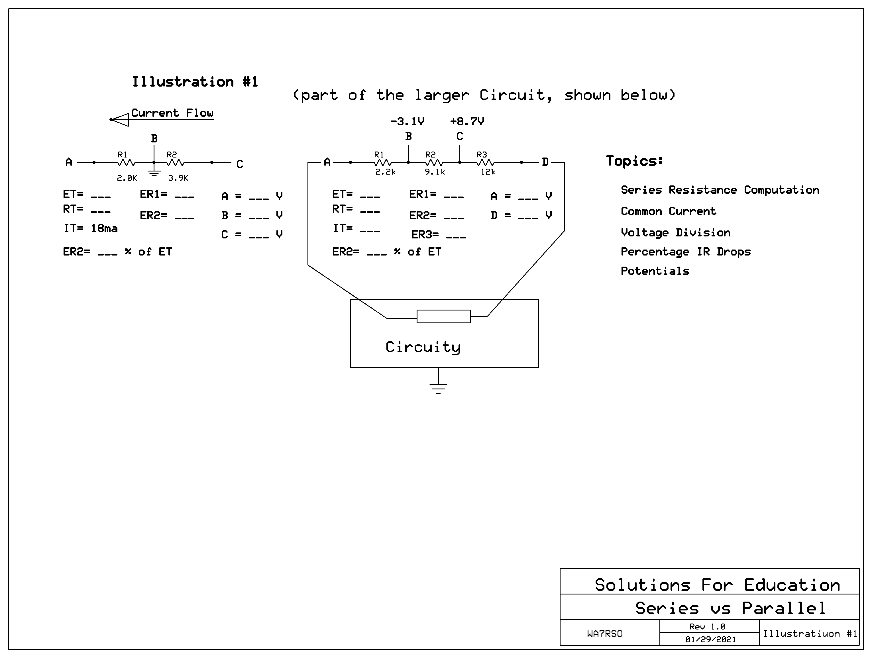
In Illustration #1 we have a conventional Series Circuit, where we have resistances that simply add, and with common current and directly proportional voltage (IR) drops.
Now consider that where Conductance is the reciprocal of Resistance, we have a whole new approach to the same circuit in Illustration #1a.
Perhaps now we understand why in Illustration #2 we use that peculiar formula of reciprocals, because in parallel considerations we can add conductances and then convert back to resistance.
Many also tend to forget that conductance is measured in "Mhos"
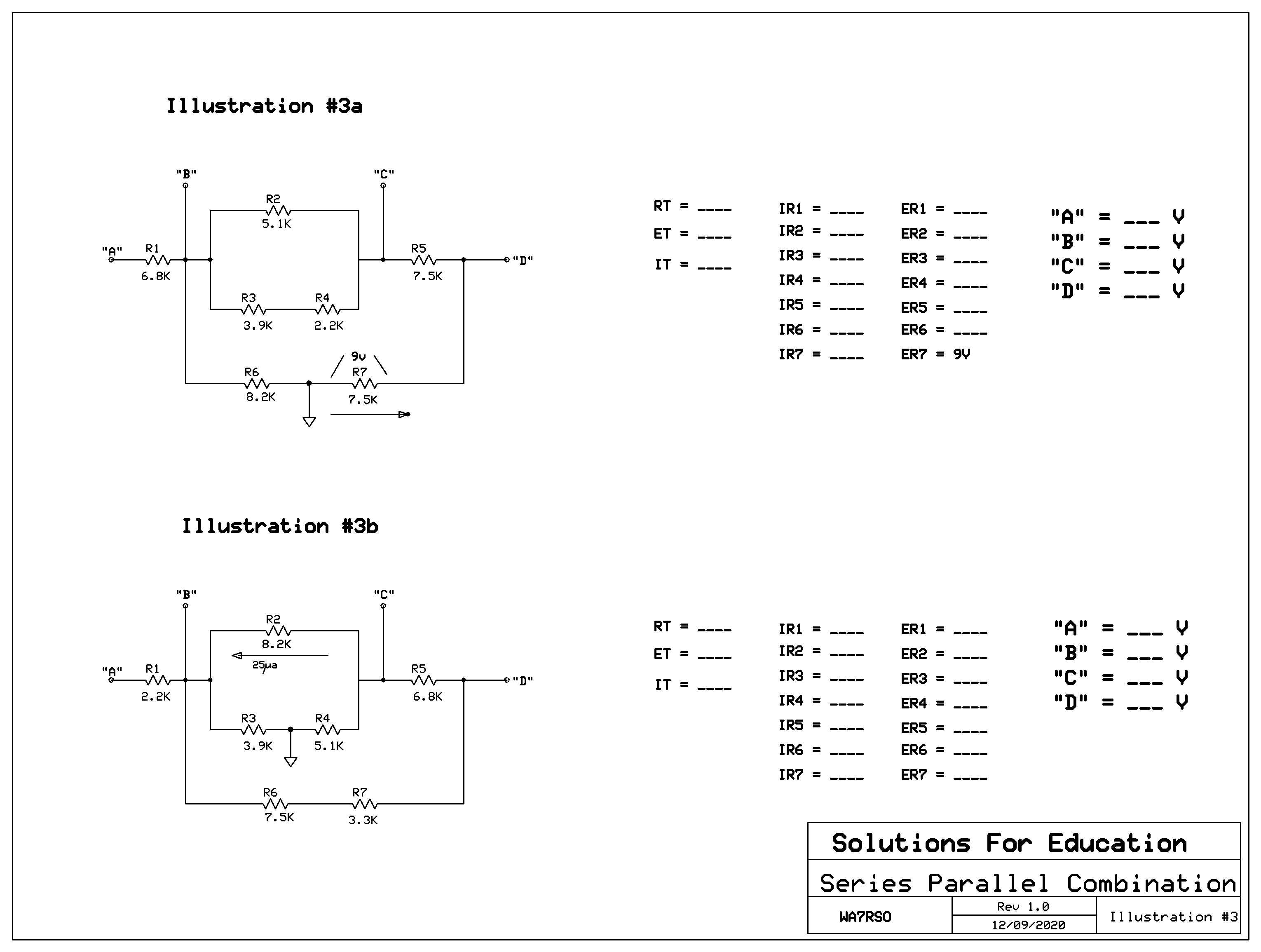
This Series-Parallel-Combination-Circuit in Illustration #3 has been my favorite for many years,, where folks have to deal with combining serial values with parallel values to determine the total resistance. Then dealing with voltage divisions and current division combinations. Finally, there are numerous "deductive problems" using single IR drops or single current allocations, or polarity potential assignments, with no ground references.
Now the infamous "Ladder Circuit"
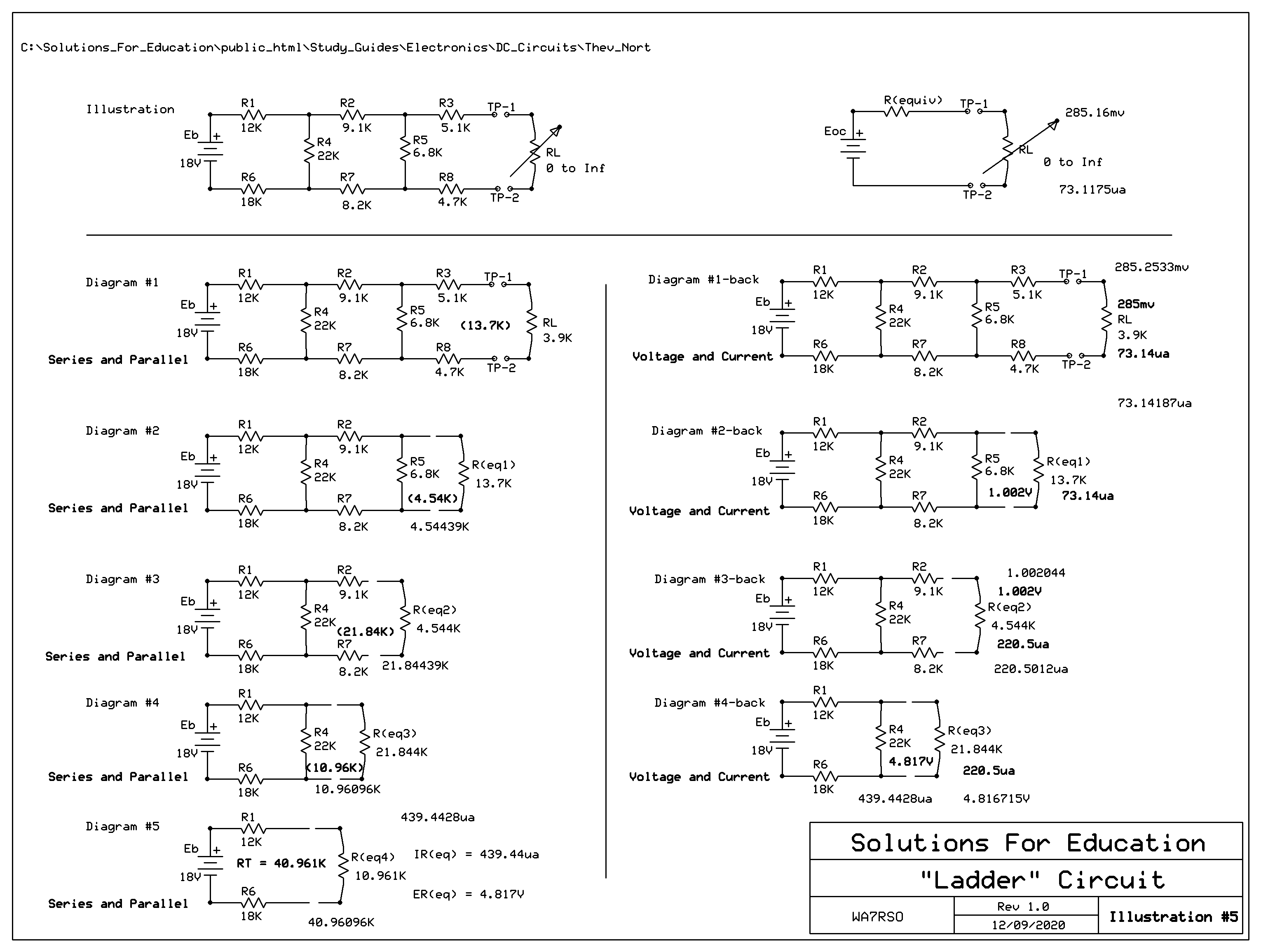
Illustration #4 shows how the Series-Parallel computations are performed down to the Total, and then common voltage and common currents are used to perform expansions back out to RL.
Illustration #5 shows more detail of the computations involved used in Illustration #4. Please note the simple schematic at the top of the page. Wouldn't it be great if that could represent the complexity of all the values in the ladder circuit, as an "equivalent" to simplify changes in the load? The answer is 'yes', and it's called the "Thevenin Equivalent Circuit Analysis" method.
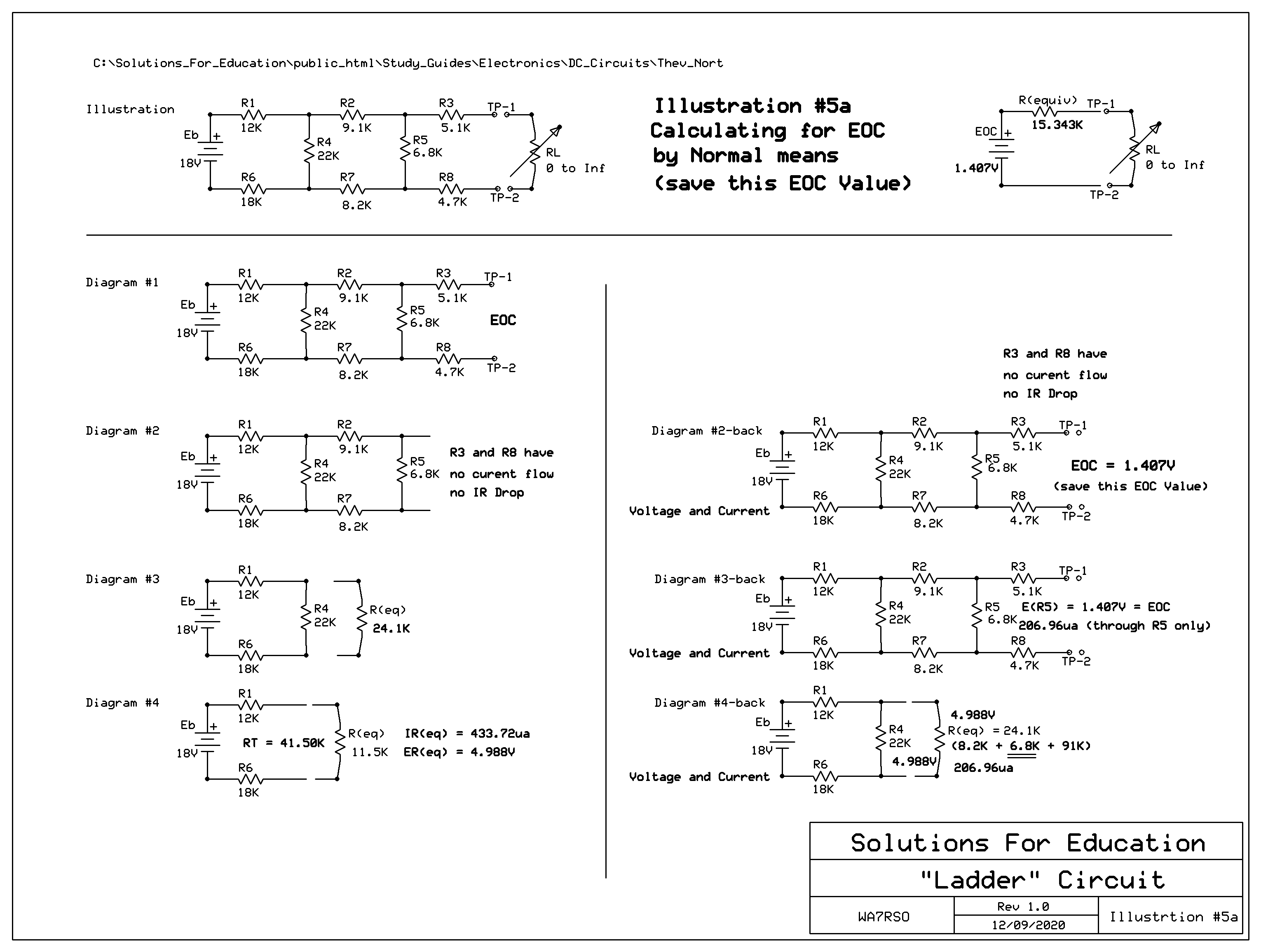
Moving on to Illustration #5a, is how this is accomplished:
First, remove the load RL to create an open circuit. Note that with no current flowing through R3 or R8, there are no voltage drops, and so we drop them out of our calculations as we compute everything toward the source, and then back out to the open circuit, which we determine to be 1.407V across the open circuit.
This is called "EOC", as in "Voltage of the Open Circuit Variety".
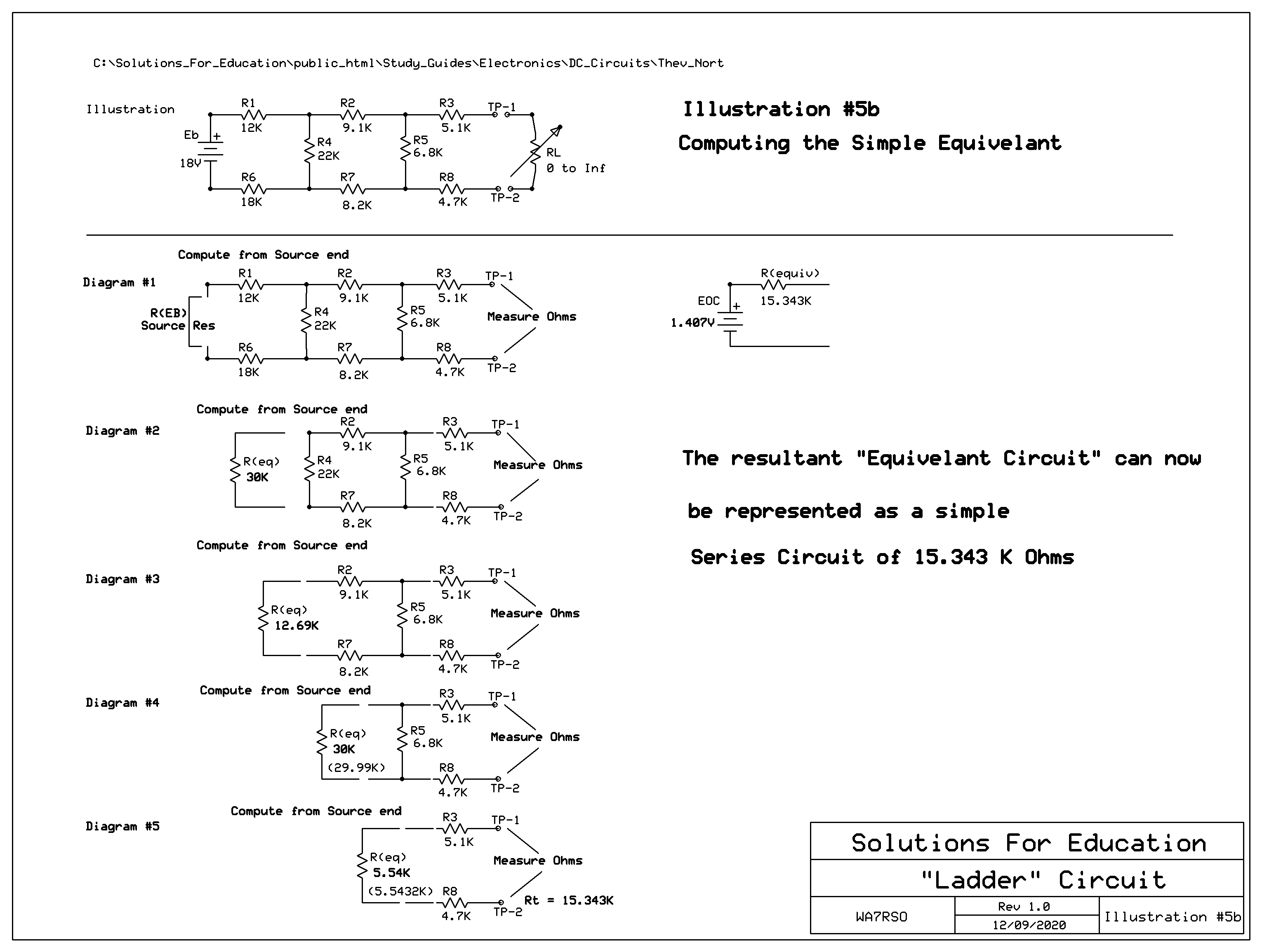
Secondly, in Illustration #5b, replace the source with it's internal resistance, and compute what an Ohmmeter would measure as a substitute for RL. This should calculate to be 15.343K Ohms, called "R-Thev". This value represents the "Equivalent Resistive Value" for the entire Ladder Circuit, minus the Load.
Thirdly, we can now compose the "EOC" as a new source voltage, and have the "R-Thev" as a simple Series Circuit to drive the Load RL.
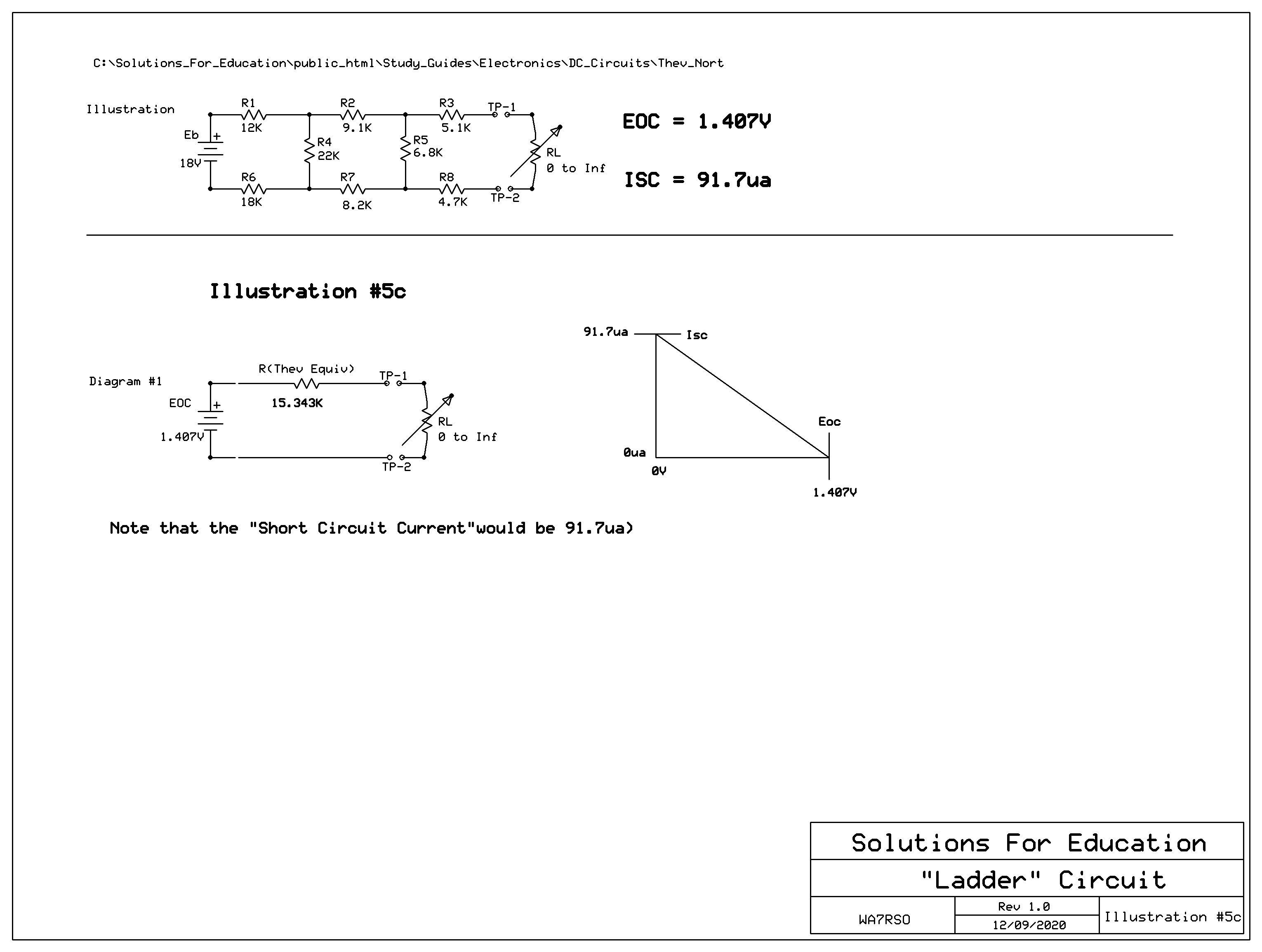
Illustration #5c shows that by presenting the load RL (of any value) we can easily calculate the resulting current and IR drop across RL. We also can now easily see that there is a set of "Min-Max" value limitations of both currents and voltages, similar to what we use as "Projected Load Lines" for either vacumn tube or transistor circuit designs.
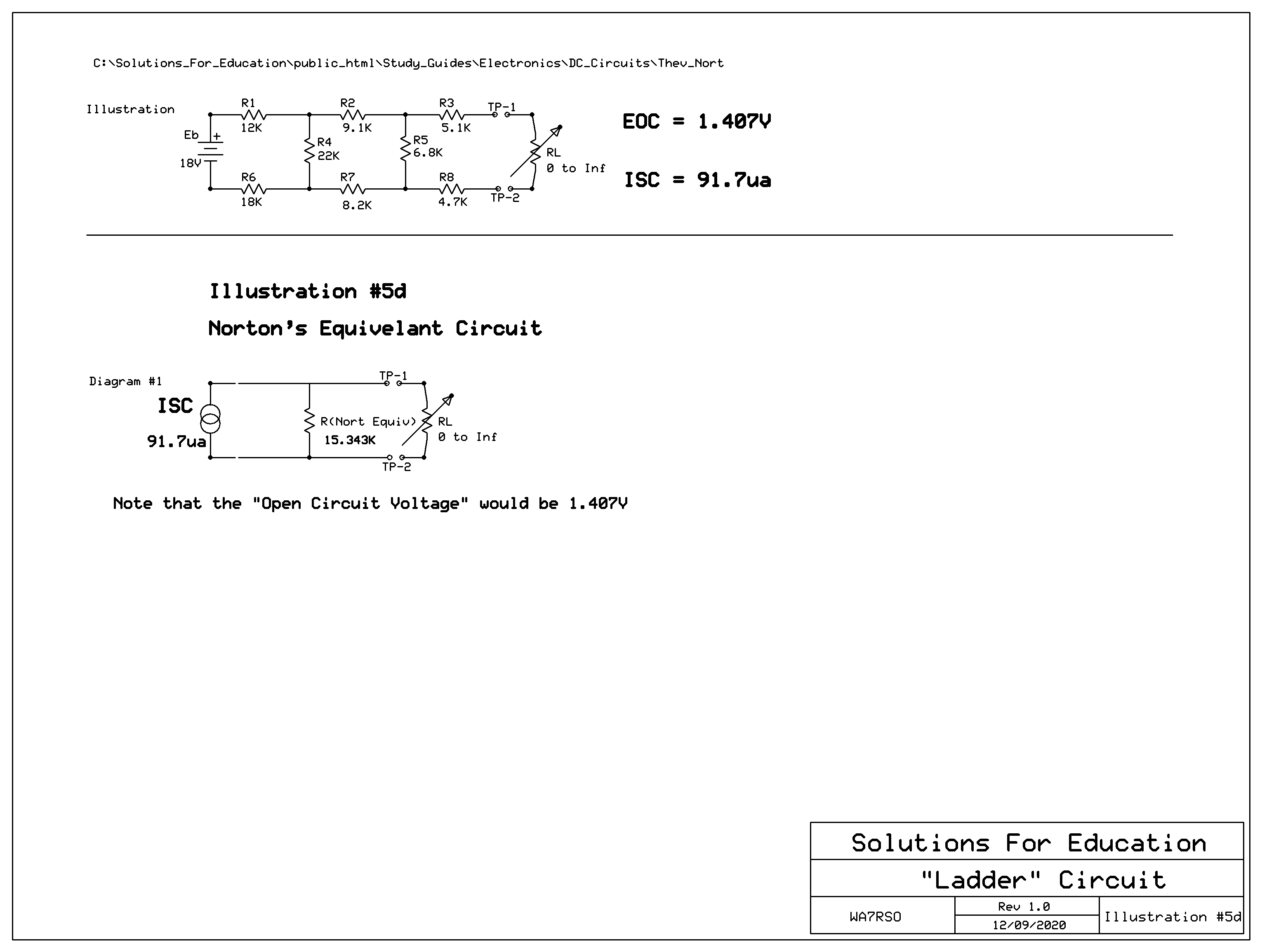
Illustration #5d allows us to see a couple of remarkable equivalent circuit considerations:
First, it turns out that in Illustration #5c, we calulate that a short circuit current would be 91.7microamps, which we call "ISC".
Secondly, there is a method of using that ISC as a "Current-Source", rather than a Voltage Source, and then placing the equivalent resistive value in parallel with the load, for current division instead of voltage division. Although this equivalent resistance was called R-Thev, here it would be called "R-Nort", even though it is actually the same equivalent circuit.
This version is called a "Norton's Equivalent Circuit Analysis", and especially note that the two are directly interchangeable one to the other.
Finally, for those who are interested, you can download and execute the "Ladder_Circuit.exe" here, which has all these initial "given" values and compute all currents, voltages and even power values. EOC and ISC are also available, with appropriate circuit illustrations."EOC" and "ISC" computations are also available. Allows changing any value and instant re-computations.