Arduino Hardware Systems
09/03/2013
Arduino MicroControllers used in my Experiments
Sketches (Routines) for these devices, with LCDs (Parallel, Serial, 2x16, 4x20)
http://www.duino.cc for source info
|
ARDUINO UNO
|
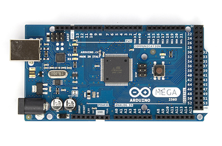
ARDUINO MEGA
|
ARDUINO DUE
|
|---|---|---|
|
Adafruit MENTA
|
NETDUINO 2
|
NETDUINO Plus 2
|

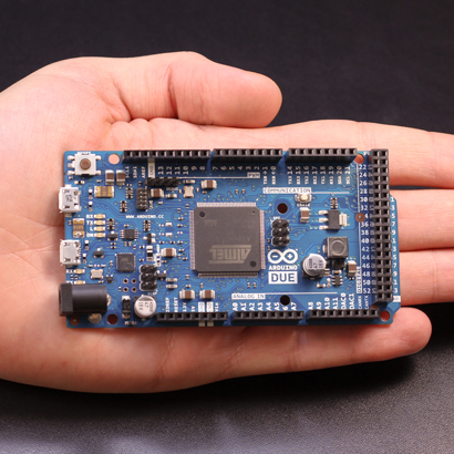


The ARDUINO DUE requires Arduino Version 1.5.0 or higher (vs 1.05) to program.
All NETDUINO Modules require the following downloads:
- Microsoft Visual C# Express 2010 or higher
- http://www.micosoft.com/express/downloads/
- Microsoft .NET Micro Framework v4.1 SDK
- http://www.netduino.com/downloads/MicroFrameworkSDK.msi
- SDK v4.2
- http://www.netduino.com/downloads/netduinosdk 32bit.exe (for 32-bit Windows)
- http://www.netduino.com/downloads/netduinosdk 64bit.exe (for 64-bit Windows)
LCD Modules used for evaluation purposes
|
Parallel 2x16 Green Backlight, White Lettering Provided with most kits, and if the wiring corresponds to the example codes, works quite well, but beware that there are a number of "correct examples", and a number of "correct wirings" that are NOT compatable with each other. See the table I provided , for a few examples of these situations. |
Code: |
|
|---|---|---|
|
Parallel 2x16 Blue Backlight, White Lettering As illustrated above, if the wiring corresponds to the example codes, works quite well, but beware that there are a number of "correct examples", and a number of "correct wirings" that are NOT compatable with each other. See the table I provided , for a few examples of these situations. |
Code: |

|
|
Parallel 4x20 Blue Backlight, White Lettering
|
Code: | |
|
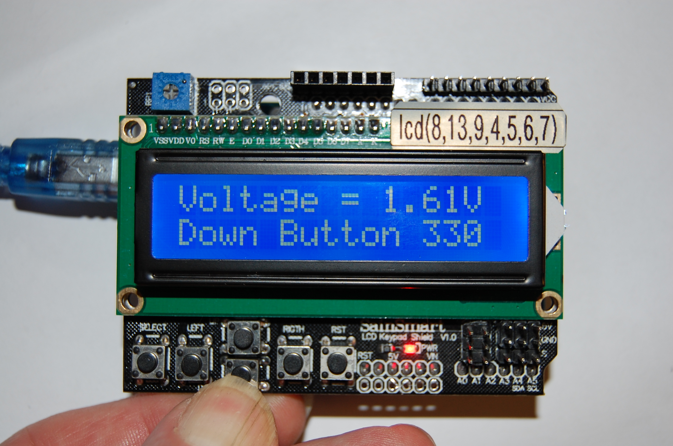
SainSmart 2x16 Blue Backlight "Key-Pad Shield" Worked quite well, with my code, but could not get the examples given to compile, except the one one "Ultrasonic-Distance-Measurement". Look at the schematic, on both their Interface-Pins, and also the way that a number of folks use an Analog Scaling of o Voltage-Divider, for determining which switch has been pressed. |
Code: |
|
| Serial 2x16 Blue Backlight, White Lettering (3-wire) | Code: | Photo: |
| Serial 4x20 Serial (4-wire) SainSmart | Code: |

|
|
Serial 2x16 Parallax (3-wire). The example for this Serial LCD worked right away, with no complications. One consideration that I ran into was that I did not find cursor positioning available. Perhaps my own ignorance. |
Code: |

|
LCD Modules as used with Arduino Modules
|
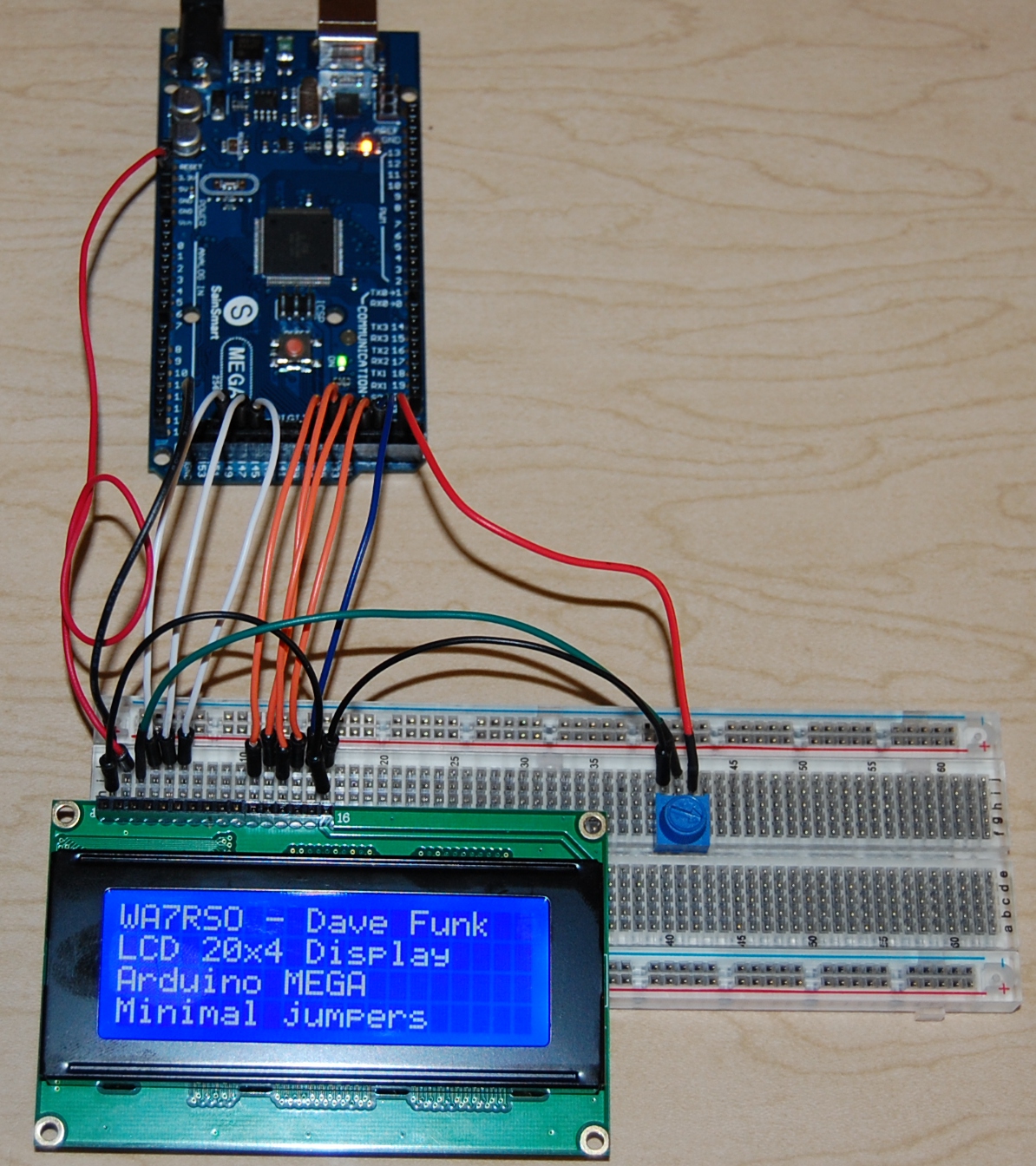
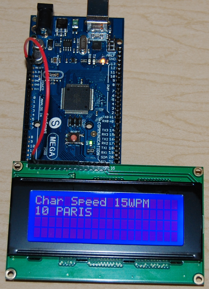
4x20 Blue Background/White Lettering, Parallel, Mounted directly on the "End" connector of a "Mega" device, requiring only a single +5V "Booster" wire. |
{code} |
|
|---|---|---|
| 4x20 Blue Background/White Lettering, Parallel, minimal direct wiring to the "End" connector of a "Mega" device, again requiring only a single +5V "Booster" wire. A "Contrast" pot was added (for variance noted between blue vs green LCDs) | {code} |
|
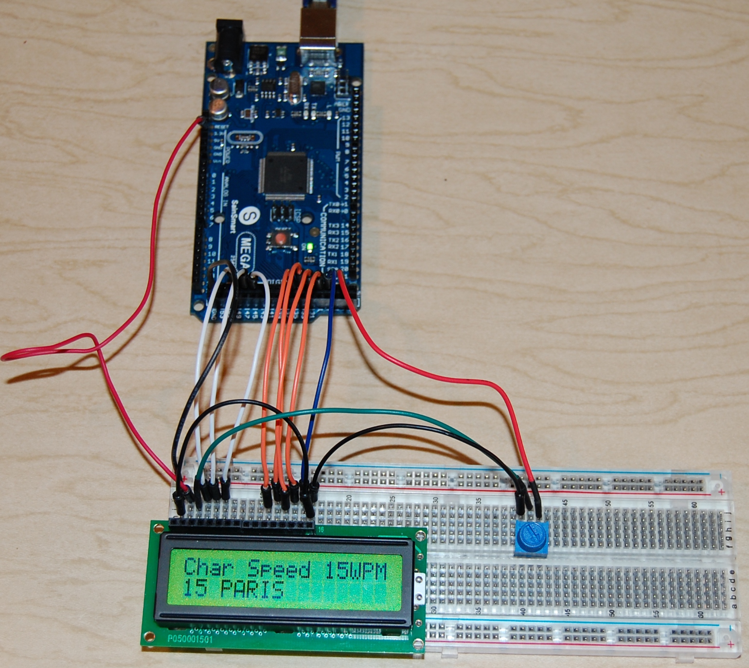
| 2x16 Green Background/Black Lettering, Parallel, minimal direct wiring to the "End" connector of a "Mega" device, again requiring only a single +5V "Booster" wire. A "Contrast" pot was added (for variance noted between blue vs green LCDs) | {code} |
|
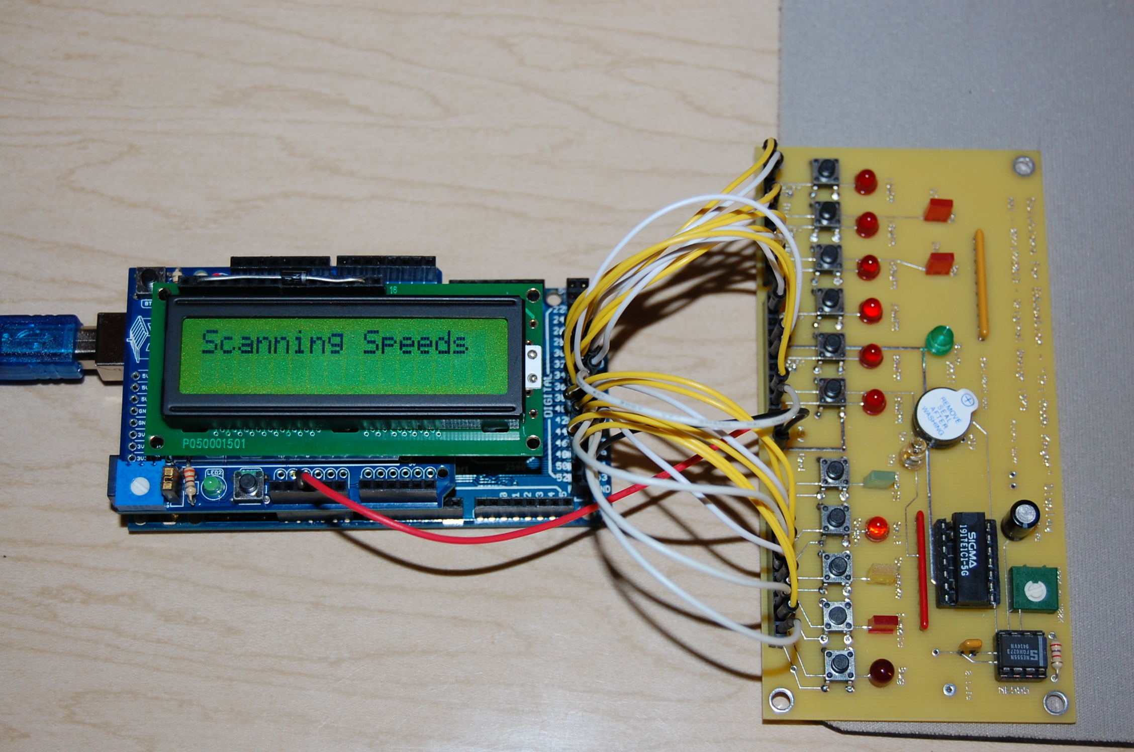
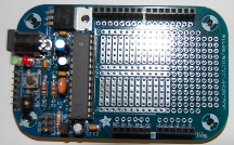
| "Top" Mounted Parallel 2x16 LCD, using a wire-wrapped Interface on a UNO Shield, mounted on a Mega device. Input and Output wiring is utilizing the multi-pin connector on the "End" of the Mega. The circuit board on the right is a "proto-type" to allow me to simulate the "Tri-Mode" Morse Code Keyer that I designed and produced with TTL devices in 1973. I was quite successful, with all "5-Modes". | {code} |
|
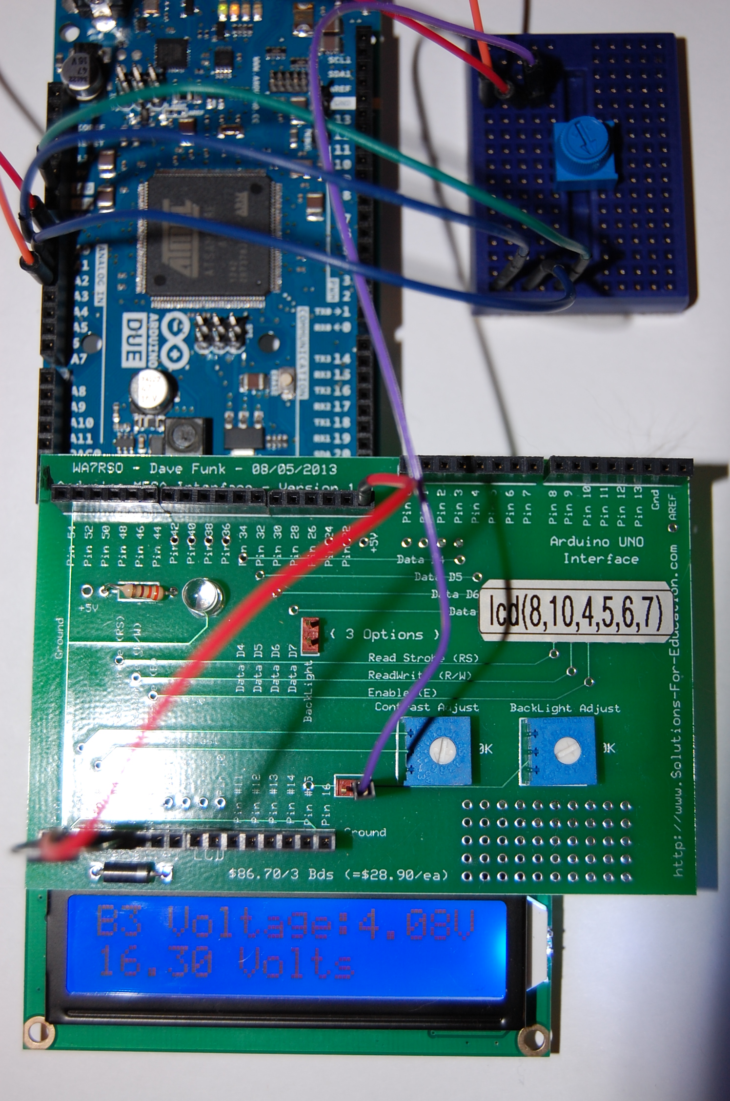
| New "Interface Board", with pre-wired straight connections to the Mega "End" for LCD display, and using a pot to simulate Battery voltages for 4 banks of batteries. Sampled voltages from the pot (0-5V) are mathematically calculated to represent battery sources up to 16.6V and solar panels up to 22V. A 2x16 LCD is shown here. | {code} |
|
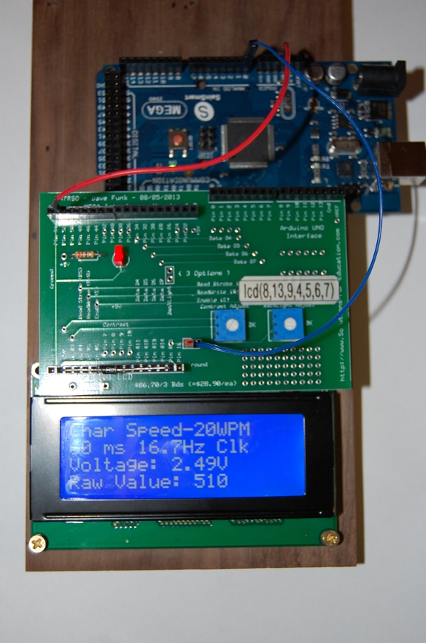
| New "Interface Board", with pre-wired straight connections to the Mega "UNO" type of requirement, for LCD display, and using a pot to simulate Battery voltages for 4 banks of batteries. Sampled voltages from the pot (0-5V) are mathematically calculated to represent battery sources up to 16.6V and solar panels up to 22V. A 4x20 LCD is shown here. | {code} |
|
| I originally could only get one of the SainSmart "KeyPad" examples to work, until I found the "Ultrasonic" one, which only partially worked. By comparing the schematic against that one example, I made my own routine, which now works quite well. | {code} |
|
| The AdaFruit "MENTA" requires either the FTDI Friend or FTDI Cable to program this module like a UNO, and then it behaves just like a UNO. Mine would not fit inside the Mint Can. | {code} |
|
See also:
Special circuit boards (from ExpressPCB) used for testing and evaluation purposes:
- ARDUINO UNO and MEGA Interface Board
- "Tri-Mode" Morse Code Keyer Simulator (switches and LED displays)
- Battery-Bank-Voltages