MFSK16
An MFSK DX Mode
A new weak signal DX mode for Radio Amateurs, employing M-ary
FSK, phase continous tones and convolutional coded FEC.
Rather than use a glossary of the dozens of technical terms used here, you will
find the definitions spread through the text. Whenever you come across the little
 symbol, hold the mouse over it to see
the definition of the preceding term.
Introduction
The Professionals
Professional communications engineers are always interested in sending
information faster and more reliably than was previously possible, if
necessary by using complex technology, greater bandwidth or higher power
to achieve this. In addition, commercial and military users for whom this
equipment is designed, are generally interested in short distance
communications with high reliability and relatively high signal strengths.
These types of communications are also generally bi-directional (full duplex)
 or unidirectional (simplex or broadcast)
 rather than one way at a time (half duplex).

The Amateurs
Although some Amateur Radio applications have similar goals, especially on VHF,
most Amateur Radio HF, MF and LF
 data communication has limited bandwidth
 available,
and usually involves half duplex operation, while the available transmitter power is
definitely limited, both by legislation and by cost. Fortunately, Amateurs
have lesser expectations of reliability, and can always postpone operation
until conditions improve, or simply talk to someone else! Amateur Radio operators also
have an almost unique interest in real-time
 communications, now abandoned by almost
all other HF services in favour of automated message techniques.
Radio Amateurs wishing to transmit data or text rather than voice (digital modes)
are often interested in very robust transmissions over very long distances,
such as from one side of the world to the other. Bandwidth needs to be kept
to a minimum, since all the Amateurs in the world share the same limited space,
and power requirements should be modest. Fortunately transmission speeds
can often also be modest, which is helpful since speed can be traded off for
improved reliability, lower power, or narrower bandwidth. This concept is the
logical concept of early work in communications theory by Claude Shannon (1947).
DX Conversation Modes
Thus there is always an interest in improving the communication performance
of low power long distance links, typically casual person to person
conversations where each person takes a turn to type on the keyboard and
transmit what he types, while the others receive and print what is sent.
Radio Teletype (RTTY)
 was used in this way for many years. Hellschreiber
 .
has recently been revived for the same purpose, and has proved to be very
effective. New techniques such as PSK31
 .
by Peter G3PLX and STREAM
 .
by Nino
IZ8BLY, have extended the performance of narrow-band links considerably.
The recent trend in these new modes, as illustrated in the last two examples,
has been to use differential PSK (DPSK) transmissions,
since DPSK offers very high sensitivity and rejection of noise. Such modes
are therefore ideal for low power. However, the biggest problems facing
very long distance (DX) communication on HF are generally selective fading
and ionospheric modulation of the signal, rather than sensitivity,
and the PSK modes do not handle these problems very well.
The MFSK Option
Amateurs have generally (a) never though of using MFSK, (b) never even heard of MFSK,
or (c) been dismissive of MFSK as being "old fashioned".
As has been clearly demonstrated by the revival and acceptance of Hellschreiber, old
ideas combined with modern techniques such as DSP
 can be very effective.
In the past, MFSK was used successfully by the British Foreign Office, the
Belgian and French military and others, using such systems as
Piccolo and
Coquelet.
Such systems were designed for high communications reliability in the
days of electromechanical equipment. These old MFSK systems provided very good
performance for the time -
robust, sensitive and reliable, with good results in fading and poor
ionospheric conditions without requiring error correction.
There are some modern military systems of a broadly similar nature
used for similar reasons.
The opportunity has now arrived to modernise the MFSK technique, creating a
new high performance yet inexpensive mode that will benefit from the advantages
of MFSK, plus the simplicity of the PC and sound card,
 and the advantages of many associated DSP techniques,
since PCs are now fast enough to perform this type of processing.
MFSK Overview for Beginners
MFSK is a technique for transmitting digital
 data using multiple tones,
extending the RTTY two-tone technique to many tones,
usually, but not always, one tone at a time.
MFSK means Multi - Frequency Shift Keying, and should not be
confused with MSK (Minimum Shift Keying). There are a number of different
techniques, using concurrent (or parallel) tones, sequential
(one after another) tones, and combinations of tones. MT-Hell
 can be either concurrent or sequential, DTMF
 tones used for telephone signalling are concurrent tone pairs, while
Piccolo and Coquelet, although using tone pairs, are decidedly sequential.
MFSK transmissions have a unique sound, almost musical, which is why
Piccolo and Coquelet received their names (Coquelet means rooster).
 Piccolo Mk 6 sample (277kB)
 IZ8BLY FSK8 sample (325kB)
 FSK16 FEC sample (184kB)
MFSK uses relatively narrow tone spacings, so remarkable data rates are achieved
for a given bandwidth - 64 bps in a signal bandwidth of 316 Hz is typical.
The following picture is a spectrogram
 of an MFSK16 signal (16 carriers)
with a spacing of 15.625 Hz and operating at 15.625 baud. The transmission operates
at 62.5 bps (about 80 words per minute!) and occupies about 316 Hz bandwidth.
The two black horizontal lines in the picture
are at 1000 Hz and 1300 Hz, and the horizontal scale is about 20 seconds. This
short transmission contains about 120 letters. MFSK16 is always operated with FEC, so the
text throughput is actually only about 42 WPM (31.25 bps).

Fig. 1. Spectrogram of an MFSK16 Signal
Advantages
MFSK has several performance advantages:
- High rejection of pulse and broadband noise due to narrow
receiver bandwidth per tone
- Low baud rate
 for sensitivity and multi-path rejection - data bit rate
higher than symbol baud rate
- Constant transmitter power
- Tolerance of ionospheric effects such as doppler, fading and multi-path
Most important of all, with an MFSK system, the error rate improves
as the number of tones is increased, so with as many as 32 tones the
performance is unrivalled. With PSK systems the opposite is true.
Disadvantages
Let's be fair - there are disadvantages to MFSK!
The main disadvantages are related to the narrow spacing and narrow bandwidth
of the individual tone detectors - drift can be a problem and accurate tuning
is essential. Good tuning indicators and AFC
 are necessary at the slower speeds. It is important that the radio transceiver
be very stable, and also that it has very small frequency offset between transmit
and receive (preferably less than 5 Hz).
MFSK also uses more bandwidth for a given text speed than a 2FSK or PSK system, but
by the same token it is therefore more robust.
How it Works
MFSK is a system where individual pulses of different radio frequencies carry information,
and the data carried depends on the frequency of the pulse. This is the same as FSK, for
example radio teletype (RTTY), but rather than two different frequencies, many more
are used - from six to 64, for example. MFSK16 uses 16 tones. Each tone transmitted is just
like a Morse code dot, but they follow each other without pause, on slightly
different frequencies.
MFSK systems generally use non-coherent detection,
 and space the many tones as closely as
possible, to restrict the transmitted bandwidth. The transmitted tones
must be spaced at a separation equivalent to the baud rate, or a multiple of the
baud rate - the rate at which the "dots"
are sent, otherwise it is difficult to separate one tone from another. This allows
the signalling to be orthogonal,
 as will be explained over the next few paragraphs.
For example, the tone carriers can be spaced by 20 Hz when keyed at 20 baud.
MFSK signals are traditionally "hard keyed", i.e. each tone starts and
stops suddenly, as in the following example.
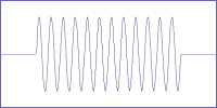
This gives the signal its characteristic frequency domain
 sin(x)/x shape,
 just the same as a Morse Code (CW) dot:
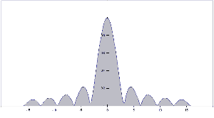
Fig. 2. The frequency domain response of a
hard keyed single tone.
The shape of the transmitted signal has a main peak, with nulls spaced either side of the carrier
frequency .
The first nulls occur at the carrier frequency � the baud rate. The humps and nulls are clearly
visible on either side in Fig. 2. If you look carefully
at the spectrogram in Fig. 1, you will see these sidelobes as grey streaks above and below the
individual dots. The big hump in the centre of Fig. 2 is the wanted signal, and it is these
that cause the black dots in Fig. 1.
Of course the dots or tone bursts are not isolated, but preceded and followed immediately by
other dots at the same or different close frequencies. Imagine then that we need to superimpose
the sin(x)/x shape of each one to see what happens. We can arrange the spacing of the tones
to achieve the best results.
Fig. 3 shows seven of these hard keyed tones superimposed, so that the nulls of
each carrier coincide with the peak of the next, to minimise cross-talk
 between channels in the receiver and therefore
allow orthogonal signalling. This occurs when the baud rate and tone spacing are
numerically the same, or at multiples of the baud rate. Fig. 3 is a spreadsheet
simulation, where the spacing is X=pi radians, and would be identical to the result
of seven tones transmitted in turn at the baud rate.
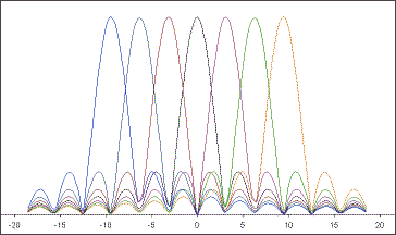
Fig. 3. Frequency domain response of seven different Sin(x)/x tones
The vertical scale in this graph is linear, 0 - 1, and the horizontal scale is
in radians, from -20 to +20, or about �12 Hz. The baud rate is assumed to be 1 Hz.
When the transmission consists of multiple tones spaced as described,
the signal broadens out across the peak, but retains the characteristic shape, as illustrated
above. When random data is transmitted, the broad peak "fills out", but the side lobes remain
obvious.
The following image shows the spectrum of a real 8FSK signal transmitting at 31.25
baud with a tone spacing of 31.25 Hz. The vertical axis in this image is logarithmic,
so the side lobes are more obvious than in the simulations above. Note that the sidelobes
are spaced 31.25 Hz because of the 31.25 Hz baud rate.
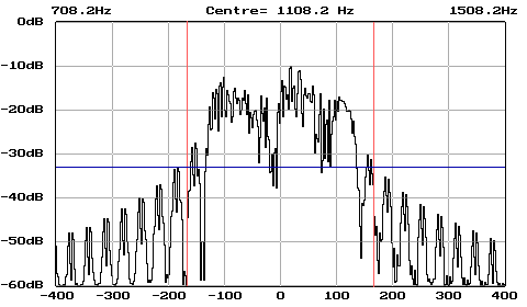
Fig. 4. The spectrum of a real MFSK transmitter
The spectrogram was taken with 0dB set at the level of a single constant tone.
A standard method of calculating the necessary bandwidth of radio transmissions is laid out by the
CCIR, and for the above transmission is 331.25 Hz (�166 Hz). Looking at the spectrum, the signal
is well below -30dB from the single tone carrier at this bandwidth (indicated by the vertical red lines),
easily exceeding the CCIR definition of 0.5% of the total transmitter power (about -20dB).
The performance (indicated by the horizontal blue line) is this good because with modern
DSP technology the signal measured above transmitted phase-synchronous tones (CPFSK).
 It so happens that this occurs naturally and easily using DSP
when the duration of each tone (the symbol period) is the reciprocal of the tone spacing
Here's another spectrogram,
 this time of an eight tone MFSK transmission,
received over 18,000 km on 18 MHz. Note the characteristic appearance!

An 8-tone MFSK signal at 18,000 km range
Convolutional Coding
Forward Error Correction is achieved by sending twice as much data as without coding,
but is done in such a way that more than twice the advantage is achieved. In addition,
the improvement in copy achieved is greater than the loss in performance by having
to use twice the bandwidth to send the data! This is called the coding gain.
The coding of the data for FEC
is very simple, but the decoding is more than a beginner can be expected
to understand. Chip Fleming has an interesting
Tutorial on Convolutional Coding
if would like to learn more.
Interleaving
One of the problems with FEC coding is that it works best if all the errors are spread
out evenly. Unfortunately interference (especially static and splatter) is burst noise,
and tends to take out data several bits at a time, which makes life very difficult
for the Viterbi decoder. To avoid this problem, we muddle up the order of the transmitted
bits using an Interleaver. Then, when bursts destroy adjacent bits, the process of
de-interleaving spreads the errors out, easing the job of the decoder.
Bits and Bauds
One of the most confusing things about MFSK is that the signalling rate is not the
same as the data rate, because each tone carries more than one data bit.
To explain this, we'll define all the terms used and show how they inter-relate.
- Symbol Rate
- The basic element of transmission in any data mode is the Symbol. In
most modes, each symbol implies a "0" or "1", but in MFSK systems, each symbol carries
information according to how many tones there are - three bits of information
for 8 tones, four bits for 16 tones, and so on.
Each MFSK tone burst is one symbol. The symbol rate is always
measured in baud (symbols/second), the reciprocal of the duration of the symbol.
- Channel Data Rate
- The data carried by the MFSK tones is inevitably coded in some way so that the "raw data"
rate may not be the same as the user input or output data rate. However, the Channel Data Rate
is always the number of bits per symbol x the Symbol Rat. The channel data rate is
measured in bits/second (bps). For example, for a 10 baud 8FSK mode (8 tone FSK) there are
three data bits per symbol, so the raw Channel Data Rate is 3 bits x 10 baud = 30 bps.
- User Data Rate
- Very often data is coded using an FEC system
 designed to reduce errors that occur due to the transmission path. For MFSK systems
the most appropriate type of FEC is the sequential type, where every user data bit is represented
in the transmission by two or more coded data bits. This ratio is the Coding Rate of the coder.
For example, if there are two coded bits for every one data bit, the Coding Rate = 1/2.
Thus the User Data Rate is the Channel Data Rate x Coding Rate.
- Alphabet Coding
- There are many ways to encode the alphabet from the keyboard for transmission.
Perhaps the most common now is ASCII (ITA-5), but ITA-2 (as used by teleprinters)
is common. MFSK16, like STREAM and PSK31, is based on a Varicode, which,
unlike most such alphabets, assigns a different number of bits to different characters,
so that more frequently used characters have fewer bits and are therefore sent faster.
The number of bits per alphabet character therefore depends on the character
frequency, just like Morse. For example:
Character   Varicode
  space      100
  a          101100
  e          1100
  E          111011100
  Z          101010110100
Thus, the alphabet coding performance depends on the chosen code, and with a Varicode,
even on the text sent:
| Alphabet |
Bits/Char |
| ITA-5 ASCII |
10 |
| ITA-2 |
7.5 |
| Varicode |
~ 7-8 |
The strength of the varicode is that the alphabet is essentially infinitely expandable.
For example, all the European accented characters are defined, and others have been added
for control purposes, that are outside the character set. The MFSK16 varicode is
not the same as the PSK31 varicode, although the technique is similar.
Another important advantage of using a varicode is that the stream of data can be much
more quickly resynchronised in case of errors, than is possible with other systems, and so
a minimum of data is lost.
- Text Throughput
-
The user is most interested in the actual usable text throughput, which is specified in
characters per second (CPS) or words per minute (WPM). Both depend on the alphabet used,
and the number of words per minute depends on the average word size. In English this is
taken for convenience to be five letters plus a letter space. So we can say that:
Text Throughput (CPS) = User Data Rate / Alphabet Bits per Character
Text Throughput (WPM) = CPS x 60 / letters per word
- Worked Example
-
Say we are using an MFSK system with 16 tones (16FSK), operating at 15.625 baud with FEC
Rate = 1/2, and an ASCII alphabet using 10 bits/character. Then:
Symbol Rate           = 15.625 baud
Channel Data Rate     = 15.625 x log216 = 15.625 x 4               = 62.5   bps
User Data Rate        = 62.5 x 1/2 (FEC RATE)                      = 31.25  bps
Text Throughput (CPS) = 31.25 / 10 CPS                             =  3.125 CPS
Text Throughput (WPM) = 31.25 x 60 / (10 x 6)                      = 31.25  WPM
This will take place in a bandwidth little more than 16 x 15.625 = 250 Hz.
- Comparisons
-
Amateur Radio RTTY operating at 45.45 baud achieves 60 WPM with no error correction,
and requires about 300 Hz bandwidth. 300 baud packet is error corrected, but is unsuited
by its design to HF conditions, and rarely delivers better than 30 WPM, and often much less.
Packet requires 1 kHz bandwidth. PSK31 operates at 31.25 baud, and in QPSK mode gives
error corrected text at 31.25 WPM approximately. It has the narrowest bandwidth, less than 100 Hz.
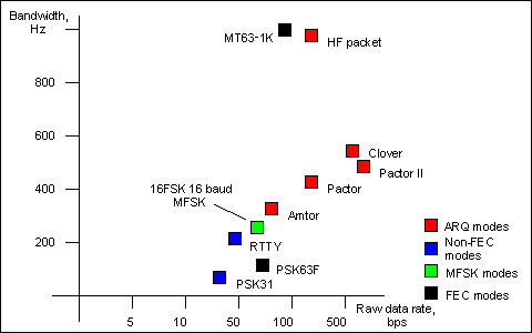
Fig. 5. Graph showing raw data rate of various digital modes
versus approximate bandwidth.
In terms of performance, of the examples given, only MFSK16 and PSK31 are considered
practical for DX QSOs. PSK31 often performs poorly on long path, and provides no improvement
when the FEC is used, so is usually used without it. MFSK is virtually as sensitive
as PSK31 in practice and is unaffected by doppler. It is also less affected by
interference, and offers effective FEC. These results are supported by ionospheric simulation
tests.
MFSK16
The first serious Amateur Radio MFSK software is now being developed - MKFS16.
Using test software by Nino IZ8BLY, initial QSOs were held 18 June
2000. The first QSO was from ZL1BPU - IZ8BLY on 18.105 MHz,
then ZL1AN - ZL1BPU on 3.560 MHz. During the initial tests, rates from 7.8 to 31.25
baud were tested, with from 8 to 32 tones! The MFSK16 specification proved to be the
best performing compromise. From test experience, here is what to expect:
-
On 17m, long path signals are normally weak and fading, but good hour-long contacts can be
made on a regular basis, with 25W transmitter power and dipole antennas.
- On 20m conditions are much more unstable, although signals are
stronger and the band open for longer. Copy is good on long path using 25W.
Nets are quite feasible.
- 80m at night is very noisy, with very bad multi-path. Copy is close to 100%
on 500mW transmitter power across town, or 10 - 25W between
New Zealand and Australia (3000 km), something not generally possible with any other
digital mode.
The software is currently undergoing an extensive series of on-air tests.
These tests build up operating experience and provide feedback to software designers
on how best to control and operate the MFSK16 mode.
Ionospheric simulation tests by Johan KC7WW on his sophisticated equipment
have shown excellent results. These can be seen on the
Documents page, and compared with PSK31. Further tests will
determine which combination of parameters should be offered in later release
versions, for example special modes for weak signal or LF, maybe even modes optimised
for MF and HF.
This new millenium MFSK16 mode includes continuous phase tones and many other improvements,
especially to the receiver. The mode is loosely based on Piccolo,
but differs in a few important ways:
- The transmitted data is bit oriented, rather than character oriented.1
- The fundamental signal is a single symbol, not a symbol pair.
- Error reduction coding is built in.
- Tone spacing and baud rates are divisions of 125.2
- The transmitted tones are phase synchronous CPFSK.
- No symbol phase or other AM information is transmitted.3
- The system can therefore potentially transmit text and binary files,
any alphabet including varicodes, and can use error coding.
- The tones and baud rates (15.625 Hz, 31.25 Hz etc) are chosen to allow
straightforward PC sound card sampling at 8 kHz sample rate.
- This means the transmitter need not be linear.
Using the receiver FFT, the transmitted carrier phase can be extracted, and from it the
symbol phase is deduced. This technique is very fast and reliable.
Of course MFSK16 is computer oriented, rather than an electromechanical
system, so will be easy and inexpensive to install, and easy to operate, with
no performance compromises. The same setup is used as for PSK31 or IZ8BLY
Hellschreiber. All you need is a Pentium class computer, a Soundblaster™ type 16-bit
sound card and Windows 95™ or newer operating system. A LINUX version and other
Windows versions should follow. The first release software to meet the specification
will probably be from IZ8BLY, for Pentium PC with Windows 95, 98 or NT™.
The specification includes:
- Accurate tuning for transceive operation using "point and click" techniques
- Convolutional coded FEC (Forward Error Correction) with interleaver for error reduction
- FFT (Fast Fourier Transform) symbol filtering and detection
- "Soft" data decoding by weighing the data from every symbol channel
- "Soft decoding" of FEC for maximimum S/N improvement
- Symbol sync recovery by measuring transitions or carrier phase in the
symbol detector FFT
- A selection of signalling speeds (and bandwidths) to suit conditions
See the Technical Specifications for details.
The MFSK Varicode is slightly more efficient than others, since more smaller codes are
available. This in turn is because the combinations "000", "0000" etc do not need to
be reserved for idle and can be used inside character bit streams. Only the combination
"001" is forbidden, as this signals the end of one character and the start of the next.
The speed on plain language text is almost 20% faster than using the G3PLX varicode.
The average number of bits per character for plain text has been measured at 7.44, giving
MFSK16 a text throughput of 42 WPM at 31.25 baud user data rate.
 DX Mode
![]() symbol, hold the mouse over it to see
the definition of the preceding term.
symbol, hold the mouse over it to see
the definition of the preceding term.


