Arduino Hardware Systems
04/23/2014
These are the ARDUINO MicroControllers and LCD displays used in my Multi-Mode Morse Code Keyers.
See my source code Sketches (Routines) for these devices, including LCDs (Parallel, Serial, 2x16, 4x20)
With these boards in constant revision, you should visit the official Arduino site for the latest availability. Some devices are no longer available.
My all around favorite is any version of the "ARDUINO MEGA", mostly because of the many extra pin-outs.
Arduinos and LCD Modules
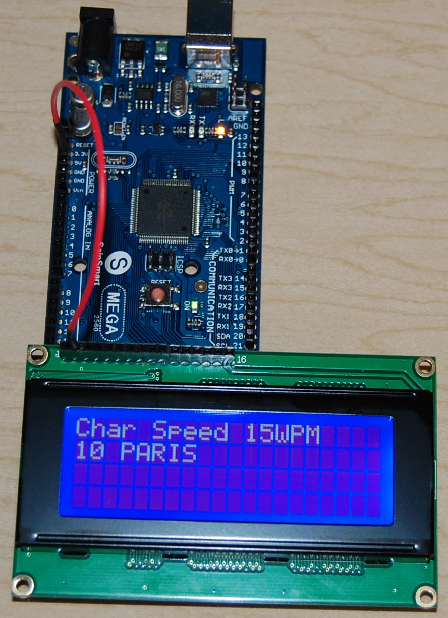
| 4x20 Blue Background/White Lettering, Parallel, Mounted directly on the "End" connector of a "Mega" device, requiring only a single +5V "Booster" wire. |
|
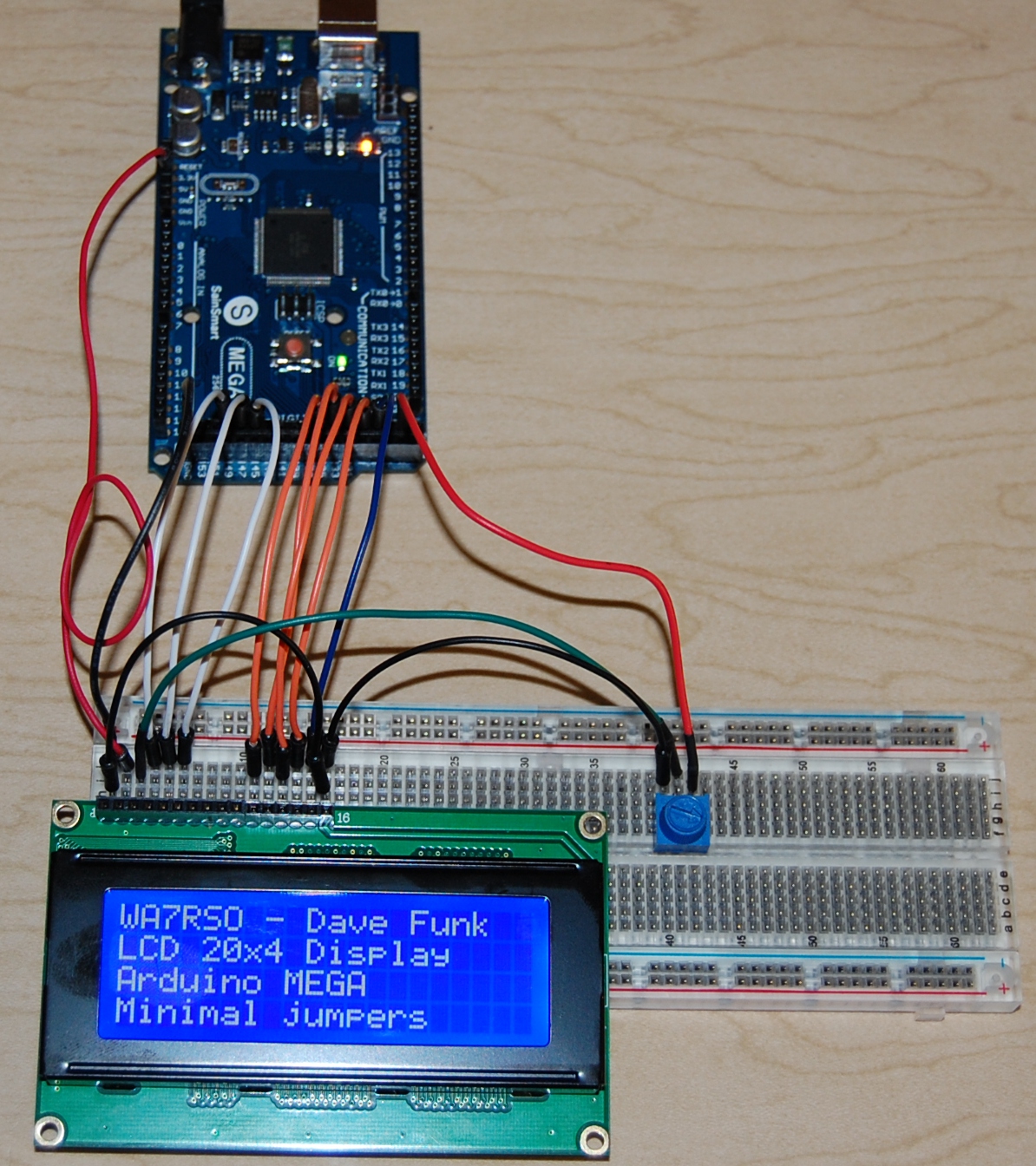
| 4x20 Blue Background/White Lettering, Parallel, minimal direct wiring to the "End" connector of a "Mega" device, again requiring only a single +5V "Booster" wire. A "Contrast" pot was added (for variance noted between blue vs green LCDs |
|
| 2x16 Green Background/Black Lettering, Parallel, minimal directl wiring to the "End" connector of a "Mega" device, again requiring only a single +5V "Booster" wire. A "Contrast" pot was added (for variance noted between blue vs green LCDs |

|
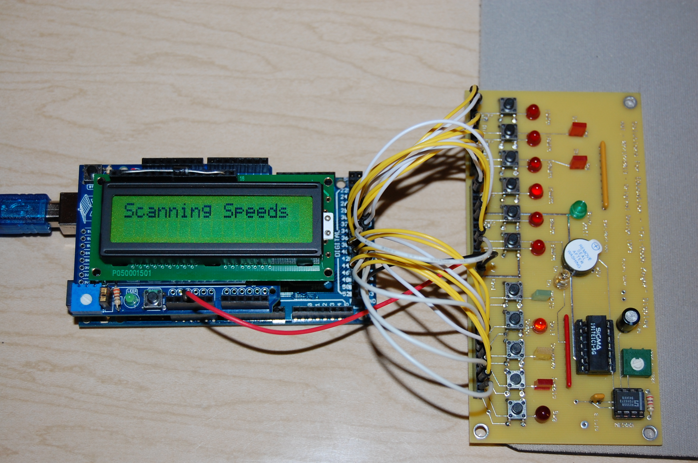
| "Top" Mounted Parallel 2x16 LCD, using a wire-wrapped Interface on a UNO Shield, mounted on a Mega device. Input and Output wiring is utilizing the multi-pin connector on the "End" of the Mega. The circuit board on the right is a "proto-type" to allow me to simulate the "Tri-Mode" Morse Code Keyer that I designed and produced with TTL devices in 1973. I was quite successful, with all "5-Modes". |
|
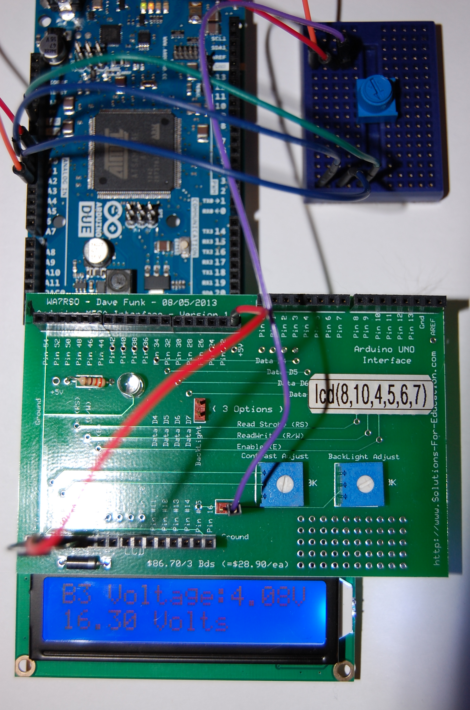
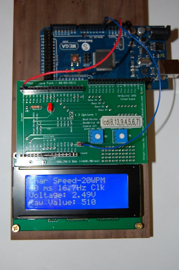
| New "Interface Board", with pre-wired straight connections to the Mega "End" for LCD display, and using a pot to simulate Battery voltages for 4 banks of batteries. Sampled voltages from the pot (0-5V) are mathematically calculated to represent battery sources up to 16.6V and solar panels up to 22V. A 2x16 LCD is shown here. |
|
| New "Interface Board", with pre-wired straight connections to the Mega "UNO" type of requirement, for LCD display, and using a pot to simulate Battery voltages for 4 banks of batteries. Sampled voltages from the pot (0-5V) are mathematically calculated to represent battery sources up to 16.6V and solar panels up to 22V. A 4x20 LCD is shown here. |
|
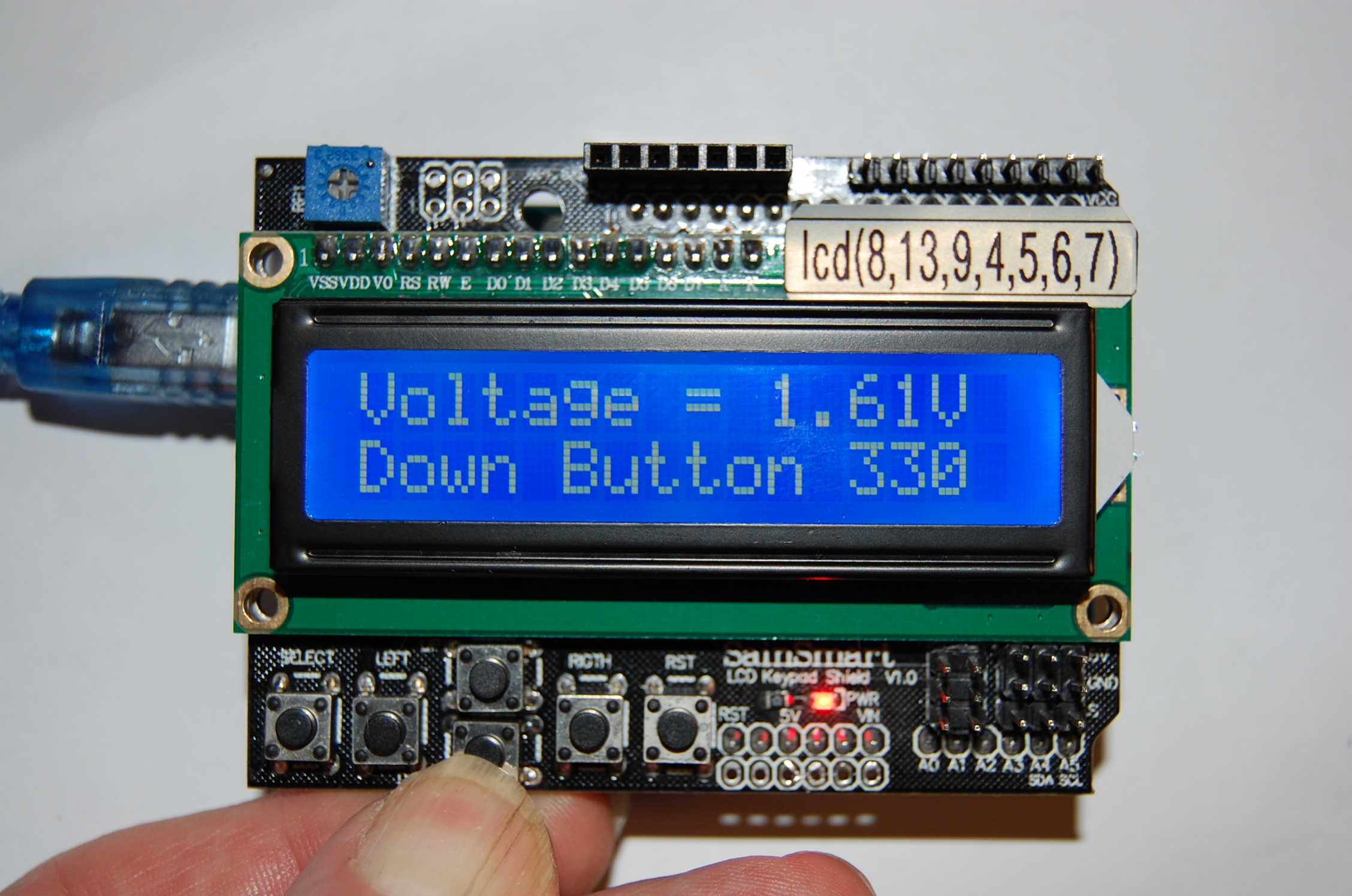
| I originally could only get one of the SainSmart "KeyPad" examples to work, until I found the "Ultrasonic" one, which only partially worked. By comparing the schematic against that one example, I made my own routine, which now works quite well. |
|
Special circuit boards (from ExpressPCB) used for testing and evaluation
- Arduino UNO and MEGA Interface Board
-
"Tri-Mode" Morse Code Keyer Simulator (switches and LED displays)
This new project is a take-off from an original design, prior to 1973, using TTL components, designed and fabricated my own etched PC Boards. To date, I have not seen any Morse-Code Keyers that incorporated the combination of Iambic, Bug Emulation, and especially the innovative "SQUEEZE-HOLD" concept. These comprised what I called a "Tri-Mode" (3 personalities) Keyer. I wanted to emulate with a "Software-Defined" Keyer, those original concepts. I was able to not only do that, but also was successful in programming into that same unit a fairly complex teaching unit as well.
- Project Notes
- Arduino Sketches
- Battery-Bank-Voltages
Back to TOPICS